
Published 2026-10-22 · DIYCarPlay Engineering Team · 23 min read
The Connector Is the Product: Why Contact Resistance Decides How Long a CarPlay Retrofit Works
A CarPlay retrofit module is usually described by what it adds: wireless CarPlay on a factory screen that never had it. What is less often described is what the addition physically is. A retrofit is a board, a harness, two antenna leads and a set of connectors, and the connector set is the part that has to survive the car. The board is tested on a bench in a factory. The connectors are tested in a moving vehicle, in heat, in the dark, for years, by a driver who has never heard of the product.
That distinction matters commercially. A module built on Linux embedded hardware with an automotive-grade Sunplus chipset, a 5GHz dual-band WiFi path and a plug-and-play harness that leaves the original screen, the original host, the original steering wheel buttons and the original reverse camera in place is a straightforward engineering proposition. The proposition becomes interesting at the point where the harness meets the vehicle, because that is where a good design and a cheap connector part ways with each other. This piece works through the connector interface in detail: what the failure modes actually are, why contact resistance is measured the way it is, why a connector that passes every bench test can still fail in a road car, and what a distributor should ask a supplier about before the first container is loaded.
The connector is a specified component, not a commodity
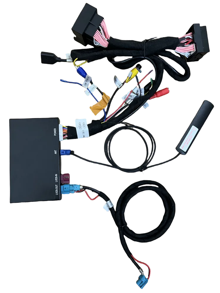
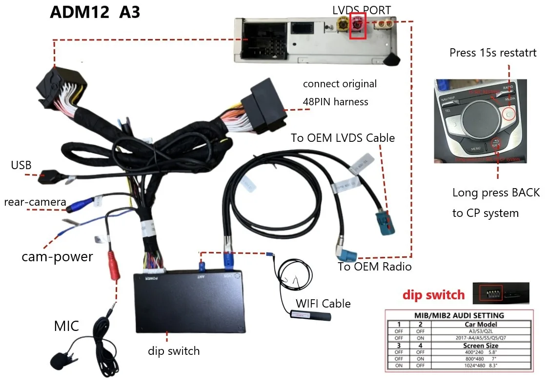
It is common to think of a retrofit as a box. It is closer to a box plus a tree of terminations, and the tree is where most of the engineering judgement sits. A typical harness for a mid-range European head unit carries a video path in and out, permanent power, switched power, ground, an accessory-detection line, a reverse trigger, a camera supply line, an audio line, a bus tap, a microphone lead and two antenna feeders. Every one of those is a separate physical joint, and every one of them is a place where the vehicle can break the product.
The consequence is that the interface has to be specified against the signals it carries, not chosen because the part is available. The video path carries a differential signal that is intolerant of a marginal contact, because a poor LVDS connection shows up as a picture artefact rather than as an error message. The power lines carry real current, and a joint that develops resistance there produces heat rather than a fault report. The reverse trigger is a low-current logic line that has to be reliable in the opposite sense: it must not chatter, because a chattering trigger makes the display flicker between two sources.
| What the joint carries | How it fails when it degrades | What the installer sees |
|---|---|---|
| Video in and out, differential pairs | Signal integrity loss before the link drops out | Flickering, snow or a picture that only fails when the car is moving |
| Permanent and switched power | Resistance rise, local heating at the terminal | Module resets under load, or a warm connector found on inspection |
| Ground | Offset reference, noise injection into the signal | Intermittent audio, noise, or a link that will not hold |
| Reverse trigger and camera supply | Chatter, or a supply that drops under load | Display switches source on its own, or the camera view drops out |
| Audio line | Signal attenuation and noise | Quiet output, or a channel that cuts in and out |
| Two antenna feeders | Loss of match, cable movement | Weak or unstable wireless link, worse on 5GHz |
None of these failure modes produce a message that says what is wrong. They arrive as symptoms, which is why the same fault gets described differently by every person who touches the car.
Keeping the factory screen rather than replacing it
Every point in that list is a consequence of one architectural decision: the retrofit adds a projection layer behind the original display instead of removing the display and putting something else in its place. The original host unit, the original steering wheel buttons, the original reverse camera and the original screen all stay in the car, and the module sits behind them doing the work of a source rather than doing the work of a head unit. An aftermarket Android head unit starts from the opposite position, replacing the panel and its mounting frame and running a general-purpose mobile operating system on it, which is a different set of failure modes in a different set of parts.
| Point of comparison | Retrofit module on the factory screen, Linux-embedded | Aftermarket Android head unit |
|---|---|---|
| What the display becomes | Original panel retained, module projects behind it | New panel, new mounting frame, different ventilation path |
| System behaviour over years | Fixed-function embedded build, no application cache to accumulate | Background services and app cache, variable load |
| Where the smoothness comes from | Automotive-grade Sunplus chipset, 5GHz dual-band WiFi path | General-purpose processor running a mobile operating system |
| Original buttons and reverse camera | Untouched, because the factory harness stays intact | Often need extra trigger and adaptation wiring |
| Service history | One unit behind the screen, one harness tree, defined connector set | Full panel to remove and refit, more looms to reterminate |
The comparison is about architecture, not about the merits of either operating system. Both approaches use similar silicon classes in some designs. The difference is how much has to be taken out of the car for the upgrade to work, and how many passive mechanical joints that leaves behind.
Connector failures are mostly open contacts, and mostly intermittent
The distribution of connector failure modes is worth stating precisely, because it shapes the whole service picture. The reference literature on electrical connectors is unusually blunt about it: the majority of connector failures result in intermittent connections or open contacts, with open circuit accounting for roughly 61 per cent of failures, poor contact roughly 23 per cent and short circuit the remaining 16 per cent. Two implications follow immediately. The first is that a short circuit is the rarest outcome and should not be the mental model of what a failing connector does. The second, and more useful, is that the largest two categories are both open-circuit behaviour, which means intermittent.
Intermittent is expensive. A unit that never works is returned in a week. A unit that works when the car is stationary and fails over a speed bump can sit in a customer's dashboard for three months, come back with a different description each time, and arrive at the distributor as a no-fault-found case. It also distorts the numbers: the same physical defect gets counted several times under different symptom labels, and the return rate for a particular model looks like a software problem rather than a connector problem.
There is a second point in the same reference material that bears directly on how an installer is trained to work. Remating or reseating a connector can alleviate the surface corrosion problem, because each cycle scrapes a microscopic layer off the contact surface and exposes fresh, unoxidised metal. In practice this means a fault that a customer describes as random will sometimes disappear after the harness is unplugged and plugged back in. That is genuinely useful as a diagnostic step. It is also a trap if it is treated as a repair: a connector that needs remating to work is a connector that is one step from needing replacement, and the customer will not bring the car back when the fault returns.
Contact resistance and why a continuity check proves nothing
Contact resistance is the electrical resistance of a mated contact pair, and it is measured in milliohms because that is the scale at which the interesting effects live. A healthy automotive signal contact typically sits in the range of a few milliohms; a degraded one can be an order of magnitude higher. A milliohm sounds negligible, and it is, until the joint is asked to carry a signal where the receiver's threshold sits close to the noise floor, or a current where the resistance turns into heat.
The measurement method is the part worth understanding, because it explains why a cheap bench check is not a substitute. Low-level contact resistance is measured by what the standards call a dry circuit: a maximum open-circuit test voltage of 20 mV at a maximum test current of 100 mA. The reason is that a contact which looks clean under a continuity tester can still be covered by an oxide film thin enough to conduct at 12 volts and too thick to conduct at 20 millivolts. Testing at a low level and a low current is what exposes the film. Typical published acceptance figures sit at 25 milliohms maximum initially with a change of 10 milliohms maximum after the environmental programme, and low-signal positions are often specified tighter still.
This is also why the durability requirement and the resistance requirement are always quoted together. A connector that measures 3 milliohms on the bench and has been cycled two hundred times is a different proposition from one that measures 3 milliohms and has been cycled ten thousand times, and the relevant standards treat the second number as the acceptance condition after the test rather than as a separate exercise. Mating cycle counts on well-specified automotive and industrial connectors run from a hundred for a small signal position to several thousand for higher-current contacts, with ten thousand being the figure used for high-cycle consumer interconnect. A retrofit harness gets plugged and unplugged more often than most people expect: at installation, at diagnosis, at a bench check before shipping, and again whenever the fault that brings a car back has to be reproduced.
Fretting: the failure that only appears in a moving car
There is a failure mode in connectors that is worth understanding on its own, because it is invisible on a bench and it is the mechanism behind a large share of in-service intermittency. Fretting is wear, and sometimes corrosion damage, at the asperities of two surfaces that are pressed together and then subjected to very small relative movement. The defining detail is how small that movement can be. The relative sliding amplitude is usually in the range from micrometres to millimetres, but it can fall as low as three nanometres, and it is repeated millions of times over the life of the vehicle.
The mechanism is self-reinforcing in a way that matters. Each micro-movement breaks and reforms the tiny areas of true metal-to-metal contact that carry the current, and each break exposes fresh metal that oxidises almost immediately. The debris that forms is usually harder than the surfaces it came from, so it acts as an abrasive and speeds the process up rather than slowing it down. The result is a contact whose resistance climbs unevenly and does not come back down, with the heat generated by that resistance feeding the oxidation that raised it. The end state can be a fully open circuit, an intermittent one, or enough localised heating to damage adjacent material.
The reference description of the effect on impedance is the number to hold on to. Contact fretting can change the impedance of a board-to-board connector from milliohms to ohms in the space of minutes when vibration is present. Not over years. Minutes. That single fact explains why a connector that measured perfectly on the bench can be an open circuit on the motorway, and it explains why the fault is intermittent rather than permanent: the impedance depends on where the vehicle happens to be and what the road is doing to the body structure at that moment.
Plating choice largely decides how fast this happens. Tin and tin-lead platings are economical and widely used, but they are comparatively soft with a readily formed oxide, and tin is the usual victim. Gold plating over a suitable underlayer resists fretting considerably better, which is why it appears selectively rather than universally. The complication is that the gold used on good connectors is itself relatively soft and thin, and under sustained micro-motion it is worn through, exposing the underlying alloy metal; once the base metal is exposed, oxidation takes over. There is a further wrinkle that catches people out, and it runs against intuition: high contact force on the mated pair, normally assumed to lower impedance and improve reliability, can make the rate of fretting worse.
Why a wire harness is a better place to land a signal than a rigid board
There is a structural reason a retrofit harness ages better than a rigid board-to-board stack, and it is worth stating because it is a design decision rather than a coincidence. Board-to-board connectors are the most vulnerable configuration in practice, because a rigid connection system has to hold two halves perfectly motionless, which is usually impossible in a vehicle. Wire-to-board connections are much less exposed to the same mechanism, because the wire half of the connection behaves as a spring and absorbs the relative movement that would otherwise be transferred all the way to the contact surfaces.
That is the physical argument for a harness-based product. A retrofit that reaches the vehicle through a cable and a tree of terminations puts a compliant element between the module and the body structure, so the micro-motion is taken up in the wire rather than in the contact. It is also the argument for strain relief and for the routing decisions that go with it, because the compliance only helps if the wire is allowed to flex where it is supposed to and is not clamped somewhere else. This is a real difference between architectures, and it is a difference a distributor can ask a supplier to explain: how the harness is terminated, how the cable is relieved, and how the assembly is secured so that the movement stays in the wire.
Vibration is the test that matters, and it is graded by where the module sits
Environmental testing for road vehicles is organised so that severity follows installation location, because location predicts the mechanical environment. The mechanical part of that framework, ISO 16750-3, covers sinusoidal vibration, random vibration, mechanical shock, free fall and gravel bombardment, and it defines different profiles for components mounted in the passenger compartment, at the engine bay edge, on the powertrain, at the wheel end, or under the floor. A centre-screen retrofit module belongs to the passenger cabin, the mildest of those profiles, and a module built for that position is not a lesser part. It is a part tested against the environment it will actually meet.
At the connector level the same logic applies, and the acceptance criteria are usually quoted in a form that makes the intent clear. A typical vibration programme subjects mated connectors to a swept sinusoidal profile with a displacement amplitude under a millimetre, at low frequency, for hours in each of three perpendicular axes, with a limit on electrical discontinuity of one microsecond. A typical shock programme applies half-sine pulses of about 50 g with an 11 millisecond duration, three pulses per direction per axis, under the same discontinuity limit. A one-microsecond limit sounds negligible and is not: a link carrying a video stream or a control channel treats a one-microsecond interruption as a dropped frame or a missed event, and a sequence of them is a fault report.
Random vibration is the harder case and the more representative one for road use, with power spectral density extending across several hundred hertz and test durations of around 90 minutes to 12 hours depending on the severity class. It is worth asking a supplier whether the module and its harness were tested together as an assembly against a random profile, or whether the connector certificates being quoted are generic part certificates. A part certificate says the connector survives a profile. It does not say that this harness, routed and secured this way, in this vehicle, survives the same profile.
What the module's own design does and does not settle
It is worth being clear about which failures a well-chosen chipset and operating system remove, and which they leave untouched, because suppliers routinely blur this line.
A fixed-function embedded Linux build has no application ecosystem to accumulate, no background service churn and no cache that needs pruning. Over years in a car, that removes a whole class of symptoms that widen without any single attributable cause. A fixed workload also means a predictable load profile and a predictable thermal output, which is a different engineering problem from managing a variable background load inside a sealed cavity. The automotive-grade Sunplus chipset supplies the headroom that makes that workload smooth, and the 5GHz dual-band WiFi path, carrying both 2.4GHz and 5GHz with the higher band preferred where the radio environment allows, keeps the mirrored display sharp at driving speed. Keeping the factory screen rather than replacing it removes the need to re-establish any of it, and leaves the original steering wheel buttons and the original reverse camera working as they were.
None of that protects a connector. A board can be the best-engineered part in the vehicle and still be returned because a terminal lost its spring tension, because a joint was crimped without the right tooling, or because a connector was mounted where the body structure could work it loose. The reference material on connectors makes the same point in a different register: insecurely mounted connectors contribute significantly to the risk of failure, particularly when subjected to shock or vibration. Securing the assembly properly is a design task, and it belongs to the same list as choosing the terminal and specifying the plating.
On the antenna side there is a second, smaller connector question that is easy to overlook. The two antenna feeders are themselves a pair of terminated joints, and the pigtail is a cable that has to be routed and fixed inside the dashboard. A 5GHz link has less margin in a congested multi-storey car park than a 2.4GHz link, which is precisely why both bands are carried on a supported module, and why the antenna routing question is a stability question rather than a cosmetic one. A joint that develops a small impedance at the antenna end will not produce a clear error; it will produce a link that degrades first at the higher band and only shows up as a complaint about picture quality.
What a distributor should ask before ordering
These are the questions that separate a harness that survives a road car from one that survives a bench test. Asking them costs a distributor nothing, and the answers are usually the fastest way to compare two quotations that look identical on paper.
- What is the plating, and how thick is it? Functional gold rather than a flash layer, specified in microns, over a named underplate. A flash layer is a decorative coating and wears through in service.
- How is the harness terminated, and by what standard? Crimped to a published acceptance procedure, with the tooling and the operator qualification behind it, rather than soldered by hand in a workshop.
- What is the specified contact resistance, and under what test conditions? The initial limit, the permitted change after environmental testing, and the test level itself. A figure quoted without a test level is not a specification.
- What is the mating cycle rating, and has it been tested on this assembly? Not the part in isolation, but the assembly in the harness.
- Which connector positions are keyed against incorrect assembly, and which carry secondary retention? A harness that can be plugged in the wrong way is a harness that will eventually be plugged in the wrong way.
- How is the strain relieved and how is the assembly secured? Movement should be taken up in the cable, and the fixing should not leave the connector carrying the load.
- Has the module and harness been tested together against a random vibration profile for the mounting position it is sold into? A generic part certificate is a weaker answer than an assembly report.
- What is the salt spray and humidity qualification on the terminals actually used? A minimum figure in hours under a named salt spray standard, not a phrase such as corrosion resistant.
The answers to those questions are what a distributor can carry into a technical conversation with an installer, and they are what turns a warranty conversation from an argument about blame into a conversation about evidence.
The symptom tells you where to look
Because the two largest failure categories are open-circuit behaviours, a fault that appears and disappears points at a joint long before it points at the radio or the phone. The following is a working triage order for an installation bay, and it is worth putting in the training material that goes out with the product.
| Symptom | Most likely interface cause | First check |
|---|---|---|
| Works parked, fails over bumps | Intermittent contact at a mated joint | Unmate and remate the harness, then re-test in the same road condition |
| Video drops but audio continues | Video path joint, or antenna feeder | Check seating of the video connectors and the antenna routing |
| Audio noisy or intermittent | Ground or audio joint | Check ground seating and the audio joint at the head unit |
| Display switches source by itself | Reverse trigger chattering | Check the trigger and the camera supply joint |
| Module resets when the engine starts | Power joint with rising resistance | Check the power and switched-power joints for seating and heat |
| Link weak only in a multi-storey car park | Antenna feeder joint or poor antenna routing | Check the feeder connections and the antenna position |
Notice what is absent from that table. Not one of those rows ends with the customer being told to check their phone, and not one of them ends with a suggestion to update software. Those checks belong, but they belong after the physical interface has been ruled out, and a service process that starts with the radio is a service process that will eventually return a harness fault as a radio fault.
Ordering terms for the hardware the connector sits on
The commercial structure around a retrofit is straightforward, and it is worth setting out plainly so that a quotation can be compared like for like. Stock modules start at 10 pieces with mixed models allowed in the same order. Private label runs start at 500 pieces per model. Full OEM programmes, where the firmware is built for one brand, start at 1000 pieces per model. The coverage spans 300+ vehicle models and series across model years 2006 to 2025, which is the number that actually determines how much of the harness catalogue a distributor needs to hold.
Samples are built in 7 to 15 days and shipped by DHL or FedEx. Volume production runs 15 to 20 days for orders of 500 pieces and above. Quotations come back within 12 hours, and they should arrive with the connector and harness specification attached rather than as a separate conversation afterwards. The sample fee is credited against the first large-volume order. Payment is by T/T or PayPal, with 30% as a deposit and the remaining 70% against a copy of the bill of lading.
The reason the harness specification belongs in the quotation rather than in a later email is simple. Once a container is loaded with several hundred units, a change to the connector is no longer an engineering decision, it is a recall. Getting the terminal plating, the mating cycle rating and the assembly test programme agreed before the first order is the cheapest version of quality control available to any importer.
Frequently Asked Questions
Is a connector really the weak point in a CarPlay retrofit module?
It is the part with the least tolerance for environment. The board is a controlled, fixed-function Linux embedded system on an automotive-grade Sunplus chipset with a 5GHz dual-band WiFi path, and it behaves predictably for years. The connectors are passive mechanical joints working inside a vibrating, heated, occasionally wet vehicle, and the reference failure distribution puts open and poor contacts at the top of the list.
Does gold plating make a real difference in a car?
Yes, and it is the reason it is used selectively. Gold does not form a surface oxide layer and does not typically corrode in air, which is what keeps the contact resistance low. It also costs more, so it is applied where the duty cycle justifies it. A thin flash layer is not equivalent to a specified functional gold thickness, and the difference shows up in a vibration programme rather than on a bench.
Can a fault be caused by a connector that measures fine before installation?
Yes, and this is the point that catches most service procedures. A contact that measures well can still be sensitive to the micro-movement described above, where impedance rises from milliohms to ohms within minutes of vibration being present. A joint also degrades after shipping, storage and handling before it ever reaches the vehicle. The acceptance condition that matters is the reading after the environmental programme, not the reading on the production bench.
What should be checked first when a retrofit unit works only intermittently?
The physical interface. Unmate and remate the harness and reproduce the fault in the same condition, because an intermittent open contact is the most common outcome and remating clears a light surface film. If the fault survives that, move to power seating, then to the reverse trigger and the video path, and only then to the phone, the radio and the software. Working through the interface first is faster, and it stops connector faults being recorded as radio faults.
How many times can a retrofit harness be plugged and unplugged?
That is a specification a supplier should be able to state. Mating cycle ratings on qualified automotive and industrial connectors run from a hundred on small signal positions to several thousand and beyond on higher-current contacts. A retrofit harness is handled more often than that number suggests, so the rating and the number of environmental cycles the assembly has actually survived are both worth asking for before an order is placed.
Next Step
Send the vehicle list that actually needs covering, and ask for the connector specification, the harness assembly test programme and the environmental reports to be attached to the quotation rather than offered afterwards. Both arrive within 12 hours, and both decide what the first container is worth before it is loaded.
Check which factory head units are covered, or request a quotation with the connector and harness specification attached.
For a technical reader, the reference entry on electrical connectors sets out the failure mode distribution, the contact plating options and the mounting and vibration considerations in more detail than a product sheet would. The mechanics of the micro-motion failure described above are covered separately under fretting.
Need the Module From This Guide?
Wholesale from 10 pcs (mixed models OK), samples in 7–15 days (DHL/FedEx express). Fitment confirmation within 12 hours.
Request Pricing Check FitmentRelated Resources
- CarPlay Collections — browse by marque family (German, British, Italian, Japanese, luxury)
- CarPlay Fitment Checker — find the module for your car
- CarPlay Decoder FAQ — 34 answers on compatibility, install and wholesale
- CarPlay Retrofit Buying Guide — platform identification & selection
- Wholesale, Private Label & OEM Program — MOQ, lead times, payment terms
- All installation & technical guides