
Published 2026-10-25 · DIYCarPlay Engineering Team · 15 min read
Why a Retrofit Module Resets on a Cold Start: Harness Length, Wire Gauge and Voltage Drop
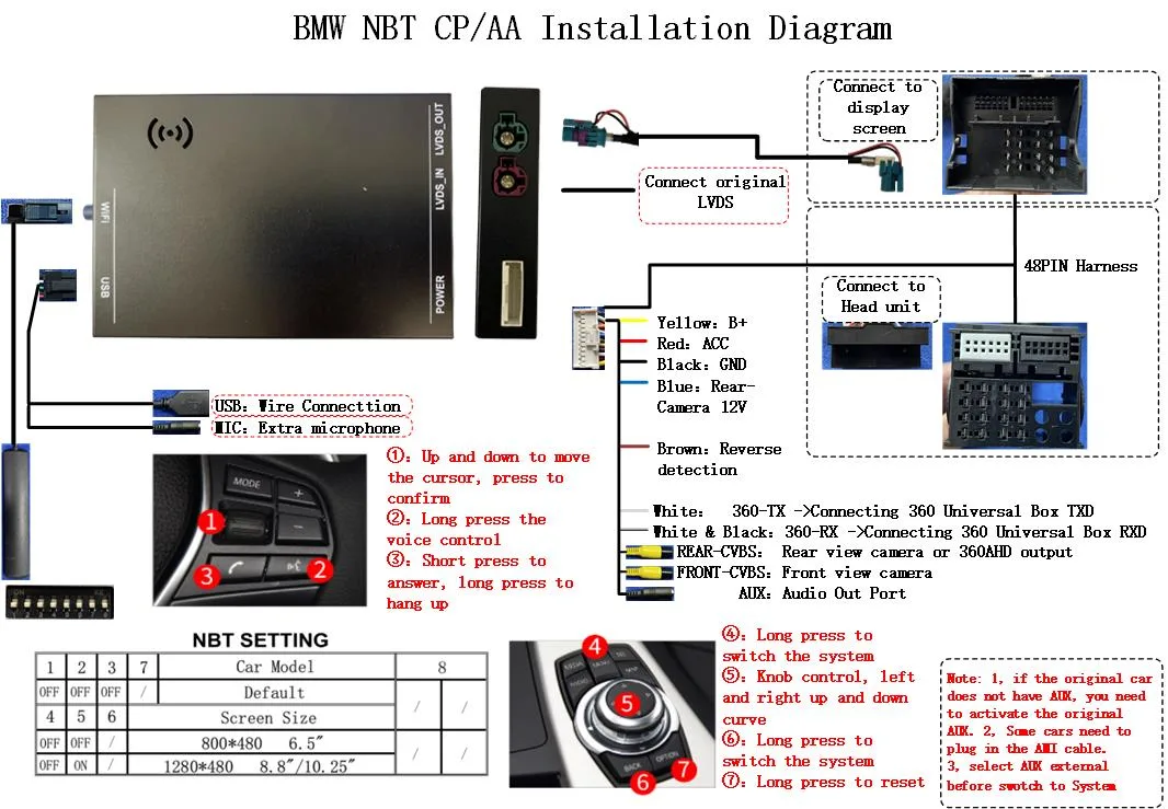
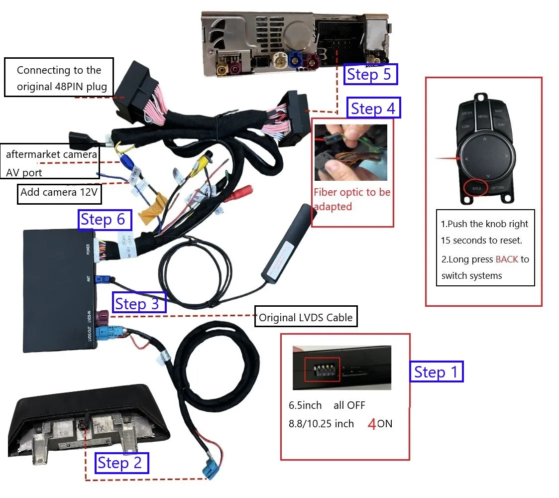
A retrofit module is a small piece of electronics that lives behind the dashboard and feeds CarPlay into a factory screen that never shipped with the feature. It draws power from the vehicle's own 12 V network, over a vehicle-specific loom that a workshop plugs into the head unit connector, and that same loom carries the reverse camera trigger, the audio tap and the CAN wake line. Every one of those connections is a copper conductor with a resistance, and that resistance decides whether the module still behaves when the engine is running.
Two terms get used loosely in this area. A retrofit module — also sold as a decoder, a CarPlay interface or an integration kit — adds wireless CarPlay to a factory head unit that was never built for it, while leaving the original screen, the original host, the original buttons and the factory reversing camera in place. A harness is the vehicle-specific loom carrying power, video, CAN traffic and accessory sense between the module and the head unit. What follows is about the power side of that loom: how long it is, what gauge it is, and what happens to it at the worst possible moment.
What the feed has to carry while the radio is working
The largest single load on a retrofit module is the radio. The link runs as 5 GHz dual-band WiFi, so 2.4 GHz and 5 GHz are both in play, and published figures for 802.11ac 5 GHz silicon put transmit current around 210 to 275 mA and receive current around 85 to 110 mA, with the radio sleeping at single-digit microamps between frames. Transmit is not a steady state — it is a burst, and the bursts land exactly when the video is moving, which is when the picture is being watched and when any complaint is most likely to be noticed.
Add the processor, the LVDS output driving the factory panel, the CAN transceiver and the audio tap, and a sensible design budget for the feed is 1.5 A with a live screen and 2.5 A to leave headroom for a radio pushing hard into a cluttered band. That headroom matters more than it sounds: a band-limited 5 GHz link will hold the radio in transmit longer, and a longer transmit means a longer peak on a conductor that has already lost some voltage on the way there.
This is where the platform choices inside the module earn their place. A Linux-embedded build performs one fixed function, so its load profile is flat and repeatable rather than spiky and unpredictable, and an automotive-grade Sunplus chipset is characterised for the voltage and temperature range a vehicle actually presents instead of being assumed to cope. The screen in the dashboard stays the factory screen either way; nothing about the display changes, and the module simply sits behind it.
The drop is arithmetic, and the return leg is half of it
Conductor resistance follows from the resistivity of copper, the cross-section of the conductor and the length of the run. Copper at 20 °C works out at roughly 0.0172 milliohm per metre for a one-square-millimetre conductor, which is the number every harness calculation starts from. The American wire gauge system standardises the conductor sizes that fall out of it, and the sizes are geometric rather than linear: reducing the gauge number by three roughly doubles the cross-section. The same reference records the conductor areas and the resistance per kilometre used in the table below, and it is the standard that the sizes are drawn from.
The part that catches people out is that a supply loop has two conductors. Current leaves the battery on the feed and comes back on the ground, so the total length of copper in the circuit is twice the distance the harness appears to span. A "two metre" harness carries four metres of conductor. Any drop quoted without that factor is wrong by a factor of two, and the error always lands in the same direction, because it makes the supply look better than it is.
| Wire gauge | Conductor area | Resistance at 20 °C | Drop over 1.5 m | Drop over 3 m | Drop over 5 m |
|---|---|---|---|---|---|
| 18 AWG | 0.823 mm² | 20.95 ohm per km | 157 mV | 314 mV | 524 mV |
| 20 AWG | 0.518 mm² | 33.31 ohm per km | 250 mV | 500 mV | 833 mV |
| 22 AWG | 0.326 mm² | 52.96 ohm per km | 397 mV | 794 mV | 1324 mV |
| 24 AWG | 0.205 mm² | 84.22 ohm per km | 632 mV | 1263 mV | 2106 mV |
Drop figures assume 2.5 A and count the supply and return conductors together. Read against the 13.5 V a running vehicle holds on the charging system, a three metre run of 22 AWG loses close to six percent of the rail before a single component sees it, and a five metre run of the same gauge loses close to ten percent. Building wiring practice treats three percent as the ceiling for a branch circuit and five percent for the whole installation, and sensitive electronics are usually held below two percent. A harness that misses those targets by a wide margin is not a marginal harness; it is a harness that will behave differently cold, hot and loaded.
The cabin runs hotter than the drawing
Copper resistance rises with temperature at about 0.393 percent per degree above 20 °C, and that is not a small correction. A loom sitting on a dashboard in a parked car in summer reaches 70 °C without difficulty, and 85 °C is within reach of a sunlit windscreen. At 70 °C a conductor carries roughly twenty percent more resistance than its catalogue figure, and at 85 °C roughly a quarter more.
Applying that to the table above changes the picture in a way that matters commercially. Five metres of 22 AWG at 2.5 A loses 1324 mV on the bench measurement and closer to 1584 mV once it has been in a hot car. The worst condition and the worst moment are the same moment: a car parked in summer, screen live, radio transmitting, with a harness that was specified at 20 °C on a bench. It is also the condition under which the electronics themselves are running hot, which is exactly when a marginal supply margin turns into a visible fault.
The engine start is the worst moment in the life of the feed
Nothing else in the life of a vehicle disturbs the supply the way a starter does. The starter motor draws hundreds of amps from the same battery, and the rail collapses while it turns. ISO 7637-2 calls this pulse 4, and the ISO 16750 series defines the engine starting profile in detail under test 4.6.3, with four severity levels held at 8 V, 4.5 V, 3 V and 6 V respectively.
In a cold crank the battery voltage can fall below 3 V for 15 to 50 milliseconds, then recover to around 6 V and stay there for several seconds before returning to normal. A warm crank is less extreme: the rail dips to 5 or 6 V, holds for about five milliseconds, then climbs back to roughly 8 V for less than a second. The module sees all of it, because the module is on the same battery the starter is borrowing from.
That is why a module that works on the bench can reset on every cold morning, and why a module fed from the accessory line rather than the constant battery line resets twice per key cycle. The module is not failing at that point; it is being asked to keep running at an input voltage below the point where its regulator loses regulation.
The behaviour after a power interruption is itself a specified requirement rather than an accident. ISO 16750-2 requires a component to return to a known, safe state after the supply is interrupted, without retaining erroneous data or dropping into an undefined operating mode. A module that reboots cleanly and comes back with the correct screen resolution and the correct platform setting has met the requirement. One that comes back with a corrupted setting, an unusable resolution or a stuck state has not, and the difference is entirely in the design of the supply front end and the reset path.
The same two conductors also carry the bad days
The power feed is exposed to far more than a clean 12 V rail. A load dump happens when the battery is disconnected while the alternator is still charging, so the energy stored in the alternator's field has nowhere to go but into the vehicle's wiring. ISO 7637-2 defines it as pulse 5, with a suppressed variant 5b sitting around 35 V for 400 milliseconds and the unsuppressed variant 5a running considerably higher — one published test figure puts it at roughly 110 V for the same 400 millisecond window on a 12 V system. ISO 16750-2 raised the requirement from a single pulse to ten, one minute apart, on the reasonable grounds that a car can see more than one of these over its life.
Reverse polarity is the other common one. A battery reconnected the wrong way puts roughly minus 14 V on the input, and the test conditions in the standards allow that to be held for more than a minute. A module without reverse protection does not survive it.
Alternator ripple is the quiet one. On top of the direct current sits an alternating component, and ISO 16750-2 defines superimposed ripple tests with peak-to-peak amplitudes of 1, 2 and 4 V, swept from 50 Hz up to 25 kHz and back down again. A module whose input filtering was designed for a laboratory supply will show it on the bench.
Protection at the input is a well-understood piece of design: a transient suppressor placed at the module's power input, after the reverse-polarity stage and ahead of the DC converter, with a short and wide path to chassis ground so the pulse has somewhere to go. Its working voltage is chosen in the 24 to 28 V band, high enough that it does not conduct during normal charging near 14 V or during a jump start from a 24 V source, and low enough that it clamps a load dump below the absolute maximum rating of everything downstream. A supplier that cannot produce the transient report for the module has not measured the thing that destroys modules.
What the module's own electronics do about it
None of this is solved by the harness alone. The front end of the module has to accept a wide input range, hold regulation through a three volt transient for tens of milliseconds, absorb a load dump without propagating it into the logic rail, block reverse polarity, and return to a defined state afterwards. That is where an automotive-grade Sunplus chipset and a fixed-function Linux-embedded build matter: the workload is bounded, the operating points are characterised, and the module has one job rather than a general-purpose operating system with services competing for the same rail.
| Point of comparison | Retrofit module on the factory screen, Linux-embedded | Aftermarket Android head unit |
|---|---|---|
| Operating system | Fixed embedded function, no general-purpose operating system layer | General-purpose operating system with an application layer |
| Load profile with a live screen | Flat and repeatable current draw | Variable, dependent on background services |
| Behaviour after a supply interruption | Returns to a defined state | Operating system restores its own services |
| Heat source area | Small module behind a display already qualified for the cabin | Full panel, larger area and nearer the windscreen |
| Long-term behaviour in the car | Same responsiveness as day one | Background state accumulates across years of service |
An aftermarket Android head unit solves the power question by relocating it: a larger panel running a general-purpose operating system draws more, runs hotter and takes longer to come back after an interruption. Neither approach is wrong in the abstract, but they are not interchangeable, and the comparison is worth making before a fleet of cars is committed to one of them. The factory screen, the factory buttons and the factory reversing camera stay in place with the retrofit approach, and that is the part a vehicle owner notices.
What to ask a supplier before ordering samples
Platform pages such as the BMW platform page list the platform code, the year range and the harness that ships with it, and the wholesale programme sets out how the volume tiers are built. Before any of that becomes an order, the electrical questions deserve answers in writing rather than assurances on a call.
- The minimum input voltage, and the behaviour below it. Not the nominal rating. What the module does when the rail falls under that figure decides whether a cold start is an event or an incident.
- Whether the feed is constant battery or accessory switched, and what the module does at ignition off.
- Harness length and gauge for each platform, and whether the quoted length is one way or a loop.
- Transient evidence. An ISO 16750-2 electrical load report covering the load dump and reverse polarity tests is worth more than a datasheet line that says automotive.
- Reset behaviour. Whether the module returns to a known state after a supply interruption, and how long that takes.
- Where the ground goes. Whether the return is shared with the head unit or taken separately, and where the ground point sits on the vehicle.
Frequently asked questions
Does harness length really matter if the module is rated for 12 V?
It matters because the module is never actually at 12 V. It sits at the charging voltage when the engine runs, it sits lower while the starter turns, and it sits lower again across a run of copper that has its own resistance. A rating describes what the module survives at its terminals; the harness decides what arrives at those terminals. A three metre run of 22 AWG at 2.5 A already removes close to six percent of the rail before anything is connected.
Why does the module reset every time the engine starts?
Almost always the supply rather than the module. During a cold crank the rail can sit below 3 V for tens of milliseconds, and a module with a narrow input window will drop out and restart. It is worth separating two causes: a reset that happens only in the cold points at the cranking profile, while a reset that happens on every start regardless of temperature usually points at the feed being taken from the accessory line rather than the constant battery line.
Can the module be fed from the accessory line instead?
It can be wired that way, and plenty of harnesses offer both. The trade is that an accessory-fed module loses power the moment the ignition is turned off, which is convenient for battery life and inconvenient for anything that expects the module to stay reachable. It also means the module experiences the cranking dip from the same accessory circuit, which is the less forgiving place to be during a cold start.
What gauge should an extended harness use?
Moving up three gauge numbers roughly doubles the conductor cross-section and roughly halves the drop, so stepping up is the direct lever. Eighteen AWG over three metres at 2.5 A loses about 314 mV on the supply and return together, against 794 mV for 22 AWG. Where an extension is unavoidable, the crimp and the connection are worth as much attention as the gauge, since a joint with a bad crimp can undo a good conductor in one place.
What is the minimum order?
Stock starts at 10 pcs with mixed models accepted in the same order. Private label runs from 500 pcs per model, and Full OEM firmware customisation from 1000 pcs per model. Samples ship in 7 to 15 days by DHL or FedEx, and the sample cost is deductible from the first large-volume order. Private label orders take 15 to 20 days for 500+ pcs.
How are orders paid for?
The standard terms are a 30% deposit with the remaining 70% against a copy of the bill of lading before shipment by T/T. PayPal is accepted for samples and small orders. Quotations come back within 12 hours, including volume tiers and the lead time for each platform named on the request.
Next step
The electrical specification of a harness is worth more attention than it usually gets, because it is the part of the retrofit that keeps behaving when the car is cold, hot and being started in the rain. The fitment checker will confirm which platform codes cover a given vehicle, and the same platform code determines the harness that ships with it.
Send the target vehicle list, the quantities and the target market through the inquiry form, and a quotation comes back within 12 hours with the platform codes, volume tier and lead time named for every vehicle on the list. Coverage spans 300+ vehicle models and series across model years 2006 to 2025, and our team can quote against a mixed-model opening order as readily as against a single platform.
Need the Module From This Guide?
Wholesale from 10 pcs (mixed models OK), samples in 7–15 days (DHL/FedEx express). Fitment confirmation within 12 hours.
Request Pricing Check FitmentRelated Resources
- CarPlay Collections — browse by marque family (German, British, Italian, Japanese, luxury)
- CarPlay Fitment Checker — find the module for your car
- CarPlay Decoder FAQ — 34 answers on compatibility, install and wholesale
- CarPlay Retrofit Buying Guide — platform identification & selection
- Wholesale, Private Label & OEM Program — MOQ, lead times, payment terms
- All installation & technical guides