
Published 2026-10-18 · DIYCarPlay Engineering Team · 15 min read
Heat, Cold and Humidity: Why a CarPlay Retrofit Module Is Qualified by Where It Sits in the Car
A wireless CarPlay retrofit module is a small box that lives behind a factory centre screen, and the thermal environment it sits in decides more about field reliability than a specification sheet suggests. The screen was designed for the cabin. The module behind it was not: it is a later addition, fitted into whatever space is left after the factory packaging, and it inherits the cabin's worst hours rather than its average.
A parked car in direct sun is a harder place to operate than almost any bench test. In Gulf summer conditions, cabin air reaches 70 to 80 °C within 30 to 45 minutes and the dashboard surface passes 90 °C. Australian measurements put a closed vehicle at roughly 65 °C within 30 minutes on a 35 °C day, climbing past 70 °C after an hour. The cavity behind the display runs hotter than a cabin reading suggests, because backlight heat, driver chip heat and enclosure heat all land in the same closed volume once the ignition is off and the airflow stops.
This piece covers what a retrofit module has to survive thermally, how the standards classify mounting positions, and what a buyer should ask a supplier before placing an order.

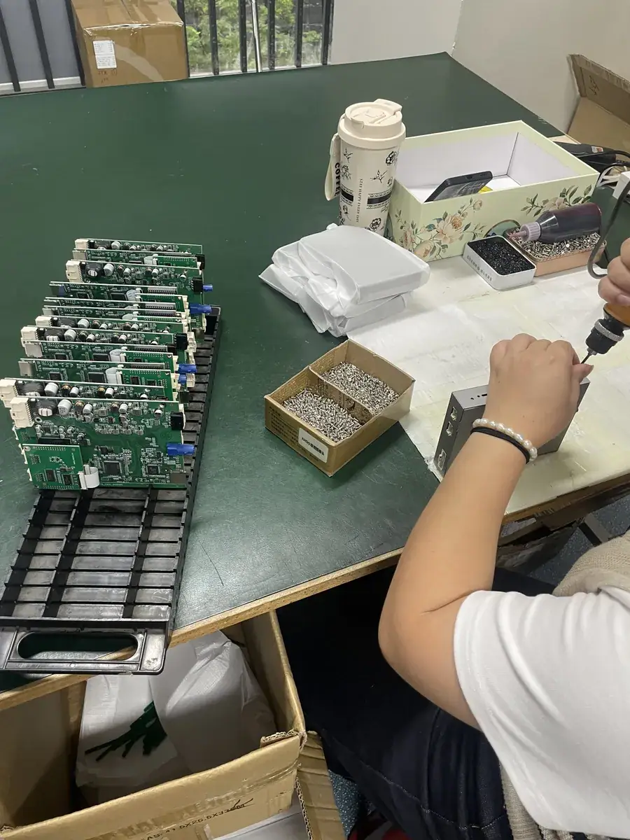
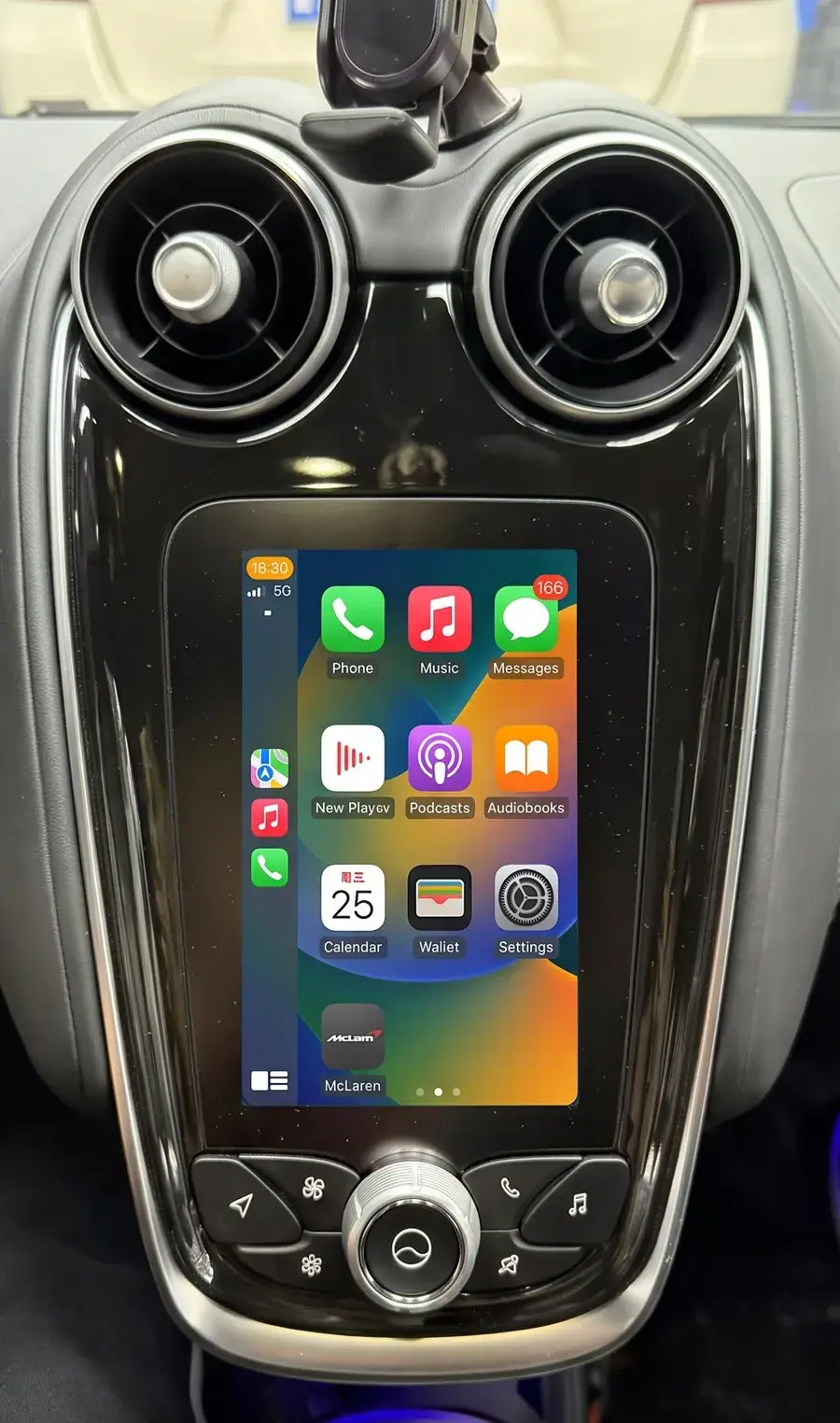
Where a retrofit module sits and why that sets its thermal class
The module connects to the factory screen's video input, taps the vehicle network for reverse and steering-wheel signals, and pulls power from the head unit harness. It is usually behind the centre stack or under the glovebox. None of those positions is a cool position. A dashboard is a black plastic box sitting under a windscreen, absorbing solar load, with the factory unit's own heat dissipation already designed around the components it shipped with.
This is the part that is easy to miss in a supplier conversation. The screen was qualified for the cabin as part of the vehicle programme. The module was qualified separately, and the qualification only means something if it was performed at the severity level matching where the module actually sits. A module tested to an engine-bay severity is not necessarily better; it may simply have been tested somewhere the product will never live.
The vehicle fitment list for a retrofit module is normally organised by head unit generation, because that is what determines the video and power interfaces. Thermal class is a separate axis, and it is worth confirming separately before an order is placed.
How the standards classify mounting positions
The automotive environmental standard that governs this is the ISO 16750 series, which sets out environmental conditions and testing for electrical and electronic equipment in road vehicles. Part 4 covers climatic loads. Its central idea is simple and useful: severity follows mounting location, because location predicts temperature, moisture and vibration.
The ISO 16750 series is divided into general conditions, electrical loads, mechanical loads, climatic loads and chemical loads. Within the climatic part, severity is graded by position:
| Mounting position | Typical ambient range | What it means for a retrofit module |
|---|---|---|
| Passenger compartment | -40 °C to +85 °C | The class a centre-screen module belongs to |
| Luggage compartment or unheated cabin area | -40 °C to +105 °C | Applies if the module sits behind a rear seat or in an unventilated boot |
| Cowl or engine bay edge | -40 °C to +125 °C | Not applicable to a head unit installation |
| Engine block or near the exhaust | -40 °C to +150 °C | Not applicable to a head unit installation |
Two practical points follow. First, a module correctly built for the passenger compartment is not a lesser part; it is a part tested against the environment it will actually meet. Second, a supplier who cannot state the severity level used for the climatic testing has not run a complete programme, regardless of what the datasheet claims.
Hot soak is not operating temperature
Three different numbers get confused in this area, and confusing them is expensive. Operating temperature is the range in which the unit functions. Storage temperature covers the powered-off period in transit, on a shelf, or in a parked car. Hot soak is the condition where a powered unit sits in a rising ambient and has to keep working while the heat builds.
Storage alone can destroy a product. Adhesives soften and creep, panel laminates grow bubbles, polarisers take stress, and connectors corrode. A module that passes every operating test can still be returned as a failure because it spent six weeks in a shipping container at 55 °C before it was ever powered on.
Hot soak is harder still. High-temperature soak testing runs the unit powered, at or near its upper limit, for an extended period, because the failure modes that matter are thermal cycling fatigue and gradual drift, not a single over-temperature event. Circuit boards, connectors and display assemblies fail differently when they are powered and working than when they are sitting on a shelf.
One further detail is worth asking about. Under high-temperature soak, the surface temperature of the enclosure typically runs 15 to 30 °C above the chamber setpoint. A module sitting behind a factory screen sees the same effect: the cavity adds to the ambient, and the module adds to itself. A datasheet quoted against ambient air understates the real figure.
What temperature cycling does to solder joints and connectors
Heat alone is often survivable. Repeated cycling is what breaks things. Glass, aluminium, plastic, copper and solder all expand at different rates. Every transition between cold and hot puts shear stress into the bonded interfaces, and every cycle repeats it.
Temperature cycling in the automotive programme runs at a controlled ramp, typically 5 to 15 °C per minute, through tens to hundreds of cycles depending on the severity grade. Thermal shock is a faster variant, above 30 °C per minute, using two chambers and a transfer basket to provoke interface failure deliberately. Both are designed to expose failures that would otherwise appear after years on the road.
The usual casualties are known and predictable: solder joint fatigue cracking from cyclic CTE mismatch, intermetallic growth in leaded joints on high-temperature dwell, adhesive creep at panel edges, delamination, and connector contact resistance drifting upward as the plating and the spring interface work against each other.
Moisture and salt arrive with the climate programme and compound the damage. Steady damp heat runs at 40 °C and 93% relative humidity for up to 1000 hours, which finds insulation breakdown and electrochemical migration on the board. Cyclic damp heat swings between 25 °C and 55 °C at 95% relative humidity on a 12-hour cycle, which forces condensation onto a colder surface and drives moisture into enclosures and connectors. Salt spray testing covers the coastal and winter-road cases, where corrosion produces a contact problem that presents weeks later as an intermittent link.
Cold water splash testing completes the picture by simulating winter road spray onto a hot component. For a distributor moving stock between a coastal port and an inland workshop in the same year, the salt and damp heat results are the ones that matter most, and they are the ones most often omitted from a supplier's test summary.
What the chipset grade changes
Component-level temperature grades come from the AEC-Q100 qualification, which places chips into grades by ambient range: Grade 0 covers -40 to +150 °C, Grade 1 covers -40 to +125 °C, Grade 2 covers -40 to +105 °C, and Grade 3 covers -40 to +85 °C. In-cabin infotainment parts are normally qualified at Grade 2 or Grade 3; engine bay parts sit at Grade 0 or Grade 1.
The grade matters less than what sits behind it. AEC-Q100 requires high-temperature operating life at full bias, high-temperature storage, temperature cycling, highly accelerated soak, moisture sensitivity levels, autoclave testing, electrostatic discharge at both human body and charged device models, and latch-up testing. Results must show zero failures, and they must be demonstrated across three independent manufacturing lots rather than one. That last requirement is the one that separates a real qualification programme from a certificate.
This is where the choice of an automotive-grade Sunplus chipset carries practical weight rather than marketing weight. Fluency on a Linux-embedded system comes from the hardware doing the work, not from software tuning, and hardware with a documented temperature envelope lets the thermal budget of the whole module be planned instead of guessed. A fixed-function embedded Linux build also holds a steady load profile, which means the heat generated is steady and predictable. That is a different engineering problem from managing a variable, background-loaded load in a sealed cavity.
| Point of comparison | Retrofit module on the factory screen, Linux-embedded | Aftermarket Android head unit |
|---|---|---|
| Thermal load profile | Fixed embedded workload, steady heat output | Background services and app cache, variable load |
| Behaviour after years in the car | Same responsiveness as day one | Cache accumulation slows the interface over time |
| Heat source area | Small module behind a display already qualified for the cabin | Full panel, often larger and nearer the windscreen |
| Cold start | Boot is short, the cabin display wakes as it does on a factory unit | Longer boot, background apps resume after start |
| Trim and cooling path | Factory bezel and vents stay exactly as built | New panel and mounting frame, different ventilation |
The comparison is about thermal behaviour, not about the merits of either operating system. Both approaches use the same silicon class in some designs. The difference is what runs continuously, and how much of it runs inside a cavity that was never sized for it.
Heat and the 5GHz link specifically
The wireless path deserves its own section, because heat degrades a radio before it degrades anything visible on screen. Three mechanisms matter.
First, crystal oscillator frequency drifts with temperature. The carrier moves, and the receiver has to correct for it continuously, which consumes margin that would otherwise be available for range.
Second, the thermal noise floor rises with junction temperature. A higher noise floor means a lower signal-to-noise ratio for the same received power, and a lower signal-to-noise ratio means a shorter reliable range and a lower usable data rate before the link starts retransmitting.
Third, protection mechanisms engage. Radio chips reduce transmit power and step down the modulation and coding scheme once a thermal threshold is crossed. The link stays up, so the fault does not look like a fault: it looks like a slow link, a stalled map, or video that gives up while audio continues.
This is why a dual-band radio, carrying 2.4 GHz alongside 5 GHz, is not simply a convenience feature. A 5GHz WiFi link carries far more bandwidth in clean conditions and is the reason a mirrored phone display stays sharp at driving speed. In a hot cavity with a metal head unit surround, the 2.4 GHz band has better propagation characteristics and more margin, and it is the band that keeps navigation audio and the reverse camera view alive when the 5 GHz path is struggling. Requiring both bands to be present on every supported module is a reasonable line for a buyer to hold.
Apple's own CarPlay connection requirements set out what the phone side of the link expects. A module that holds a stable 5 GHz dual-band WiFi connection through a cabin soak test satisfies the harder half of that contract, because the phone has no way to compensate for a module that has throttled its radio.
Where a module should and should not be mounted
Most thermal field failures trace back to siting rather than to component selection. A module installed into the hot cavity behind a sealed factory screen, with no airflow path and no conduction path into the head unit chassis, will run hotter than any test chamber number suggests.
A sensible siting rule is to give the module a conduction path rather than leaving it suspended in air, to keep it away from a screen back that is already dissipating, and to avoid sealing it into a fully enclosed void with no air movement at all. Where a vehicle offers a ventilated cavity behind the centre stack, that cavity is a better location than a sealed glovebox recess. The installation manual should state the intended position rather than leaving it to the installer.
For an installer working to a workshop standard, this translates into a simple check. After a fitment, the module should be confirmed to be running, not merely powered, and the check should be repeated after the vehicle has stood in direct sun. A module that works in the morning and fails in the afternoon has a siting or thermal problem, and it will not be fixed by a firmware update.
What to ask a supplier before ordering
Six questions separate a qualified module from a packaged one, and all six can be answered in writing before a purchase order is raised.
- Which ISO 16750 severity level was the climatic programme run against, and which mounting position was assumed?
- Was the high-temperature soak performed powered and functional, or only as a storage test?
- How many temperature cycles, at what ramp rate, and were the units functional throughout or only at the endpoints?
- Are damp heat and salt spray results available for the specific model, rather than only for a related product?
- What AEC-Q100 grade does the chipset carry, and was it qualified across three manufacturing lots?
- Has the 5 GHz dual-band WiFi link been measured inside a heated cabin cavity rather than on an open bench?
A supplier who answers all six with test report references has already done the work. One who answers with adjectives has not, and the difference shows up in the returns column two summers later.
Frequently asked questions
Does a module need the same temperature grade as the factory screen?
Not the same, but the same order of severity. The screen was qualified as part of the vehicle programme at the passenger-compartment level of -40 °C to +85 °C. A retrofit module needs its own qualification at that same level, because it is a separately sourced component with its own heat sources and its own mounting position.
Will a module survive a parked car in a hot climate?
A module built and qualified for the passenger-compartment severity is intended to. The qualification covers the soak conditions, and the in-cabin design keeps the radio working by falling back to the 2.4 GHz band when the 5 GHz path degrades. What it does not cover is a unit mounted in a sealed pocket with no air movement, which no qualification can compensate for.
Does cold weather cause failures too?
Cold affects a different set of materials. Brittle plastics, higher contact resistance in connectors, and stiffened adhesives are the usual cold-start issues, and the -40 °C lower bound exists because winter markets need it. Nordic and Canadian distribution routes should ask for the low-temperature functional results specifically.
How much does the aftermarket Android option change the thermal picture?
It changes the load profile rather than the temperature. A full panel running background services generates variable heat in a larger area, and the cache accumulation that shows up as sluggishness after a year is the same behaviour that shows up as extra heat. Neither approach is disqualified by temperature; the mounting and the sustained workload decide the outcome.
Why does a slow link appear only in hot weather?
Thermal throttling on the radio. Oscillator drift and a higher noise floor consume link margin, and once a threshold is crossed the transmitter reduces power and drops the modulation scheme. The link stays connected, so the symptom looks like bandwidth rather than like a fault. Testing in a heated cavity is what separates a thermal design problem from a signal coverage problem.
Commercial terms
Coverage runs to 300+ vehicle models and series across the 2006 to 2025 model years, which is where the head unit generations worth retrofitting actually sit. Minimum order is 10 pieces with mixed models allowed in one shipment, private label production starts at 500 pieces per model, and full OEM firmware customisation starts at 1000 pieces per model.
Samples take 7 to 15 days by DHL or FedEx. Production runs of 500 pieces or more take 15 to 20 days. A written quotation comes back within 12 hours of the vehicle list, quantities and destination market arriving. Payment is 30% deposit with the remaining 70% against a copy of the bill of lading, by T/T or PayPal. A sample fee is credited against the first large-volume order.
The thermal questions above are worth asking before the first order rather than after the first returns. Send the vehicle list and the target market through the inquiry form, and the test report summary for the specific model can be included with the quotation. Full wholesale terms and MOQ tiers are published for comparison.
Need the Module From This Guide?
Wholesale from 10 pcs (mixed models OK), samples in 7–15 days (DHL/FedEx express). Fitment confirmation within 12 hours.
Request Pricing Check FitmentRelated Resources
- CarPlay Collections — browse by marque family (German, British, Italian, Japanese, luxury)
- CarPlay Fitment Checker — find the module for your car
- CarPlay Decoder FAQ — 34 answers on compatibility, install and wholesale
- CarPlay Retrofit Buying Guide — platform identification & selection
- Wholesale, Private Label & OEM Program — MOQ, lead times, payment terms
- All installation & technical guides